
Level of Development Expectations for MEP Models
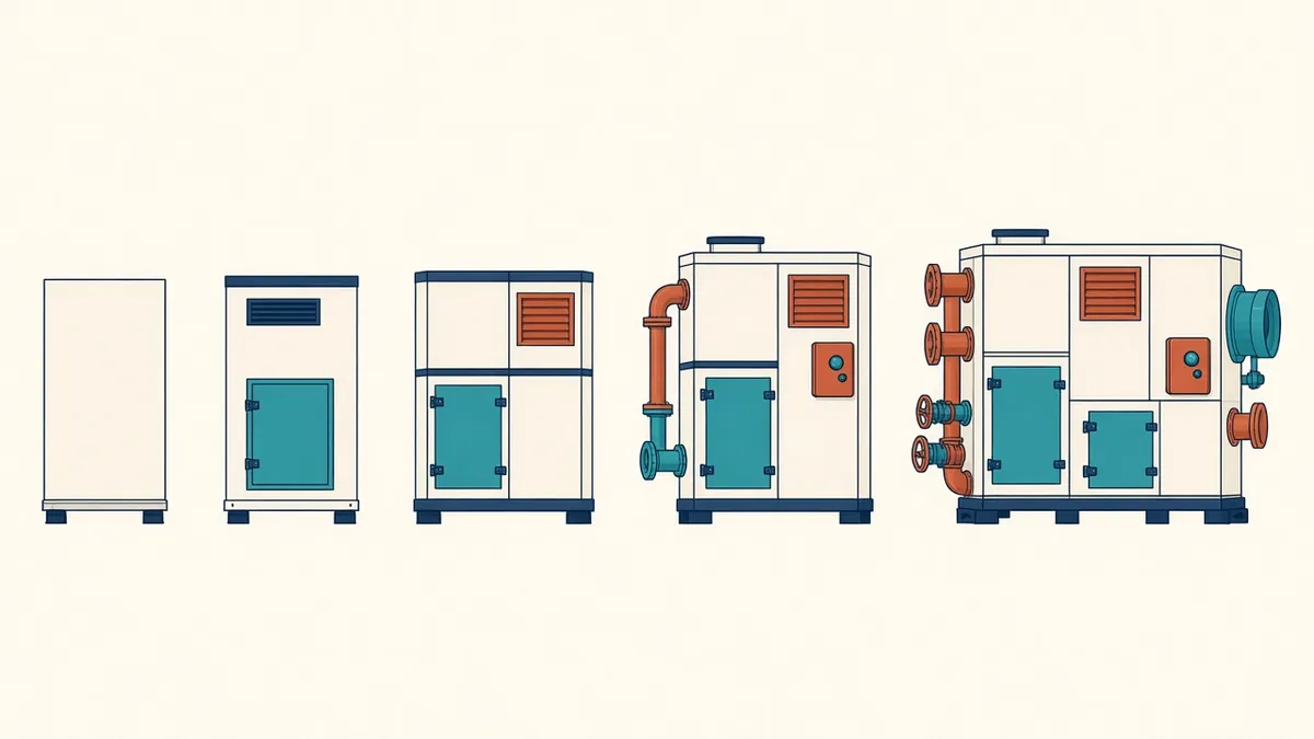
"Coordinated" means very different things at concept and at shop drawing stage. LOD expectations make that explicit.
MEP models develop through a project. Early models show strategy and main routes. Later models show detailed sizes, routes and fittings. Agreeing what each model should contain at each stage helps coordination work and avoids false expectations.
Level of development
Level of development (LOD) describes how far an element's geometry and information have been developed, and how much others can rely on it. The BIMForum LOD Specification is a widely referenced guide, describing levels such as LOD 100, 200, 300, 350 and 400. In the UK and ISO 19650 contexts, teams often describe the level of information need instead.
Typical progression for MEP
- Early design: zones, indicative routes, plant space and riser allocations
- Developed design: main ducts, pipes and containment with approximate sizes and routes
- Technical design or construction documents: sized services with coordinated routes, main fittings and equipment
- Construction coordination: detailed models with fittings, supports, insulation and access, often by subcontractors
Exact expectations vary by project and contract.
- LOD 100Symbol or generic mass. Shows that an element exists, with approximate area or volume.
- LOD 200Generic system with approximate size, shape, location and orientation.
- LOD 300Specific size, shape, location and orientation that can be measured from the model.
- LOD 350Level 300 plus the interfaces and connections with nearby elements and systems.
- LOD 400Enough detail for fabrication and installation.
Why it matters for coordination
Clash detection is only meaningful when models are developed enough. Running detailed clash tests on early models produces results that aren't useful. Agree which clash tests apply at each stage.
Insulation and supports
Insulation, hangers and supports affect space but are sometimes not modelled until late. Agree whether they'll be modelled or allowed for with clearance tests.
Equipment
Equipment models should show correct size and maintenance clearances when coordination depends on them. Manufacturers' content can help later in design.
Who models what
Design engineers and contractors may both model MEP at different stages. Responsibility matrices in BIM execution plans clarify who models each element and when.
Information, not just geometry
Models often carry data, such as system names, sizes and equipment references. Agree what information is needed for coordination, schedules and handover.
Write it down
Check models against requirements
During model reviews, check that elements meet the agreed level. Flag gaps early.
Avoid over-modelling
Modelling more detail than needed takes time and can make models heavy. Model what's needed for the purpose at each stage.
Review at milestones
At each design milestone, check MEP models against the agreed requirements before running coordination tests. Gaps found early are easier to close.
Clear LOD expectations make MEP models reliable for coordination and help teams focus their effort where it matters.
If your team needs extra production capacity for work like this, take a look at our Architectural production services, or tell us about your project.
Related articles

Level of Development (LOD) Explained for Architects
What each LOD means in practice, and how to agree the right level for each stage.
Read more →
Writing a BIM Execution Plan That Gets Used
What goes in a BEP, and how to make it a working document.
Read more →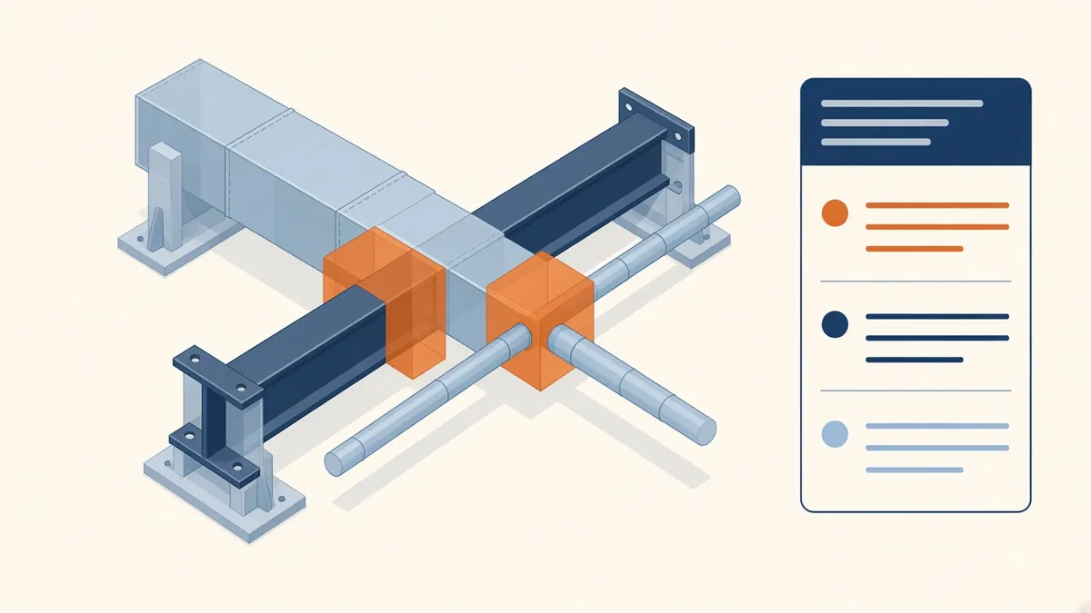
Clash Detection Explained for Architecture Teams
Hard clashes, clearance clashes and how to turn clash reports into decisions.
Read more →