
Part L Energy Compliance: What Drawings Need to Show
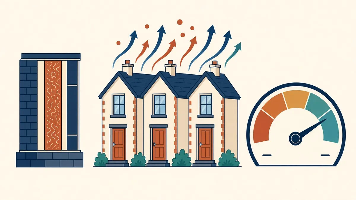
Part L is about conservation of fuel and power, and the drawings need to support what the energy calculations claim.
Part L of the Building Regulations in England covers conservation of fuel and power. Its guidance is published in Approved Document L, in two volumes, for dwellings and for buildings other than dwellings. Part L compliance relies on calculations, but drawings and specifications need to support them.
Compliance calculations
- Dwellings: typically use the Standard Assessment Procedure (SAP)
- Other buildings: typically use SBEM or approved dynamic simulation software
Calculations compare the design against targets set in the regulations. They're usually prepared by an energy assessor or engineer.
Recent changes
The 2021 edition of Approved Document L, which took effect in 2022, raised standards for new buildings and introduced new metrics. Further changes are expected through the Future Homes and Buildings Standards. Check the current position for each project.
Fabric information on drawings
- Wall, roof and floor build-ups
- Insulation types and thicknesses
- Target U-values where shown
- Window and door specifications or references
- Thermal bridging details at key junctions
Thermal bridging
Junctions contribute to heat loss. SAP calculations use psi values for junctions, either default values or calculated ones. Details should support the values used.
Air tightness
Part L includes air permeability requirements and testing. Drawings should show the air barrier line and how it's maintained at junctions, penetrations and openings.
Consistency matters
The biggest risk is inconsistency between drawings, specifications and calculations. For example:
- Insulation thickness reduced in a later revision
- Glazing specification changed
- Junction details updated without updating calculations
Design stage and as-built
For dwellings, calculations are typically submitted at design stage and updated as built. Building control expects the as-built calculations to reflect what was actually constructed, with supporting evidence.
Overheating
Approved Document O addresses overheating in new residential buildings. It can affect glazing sizes, shading and ventilation, so consider it alongside Part L.
Ventilation
Approved Document F covers ventilation, which interacts with air tightness. Tighter buildings need well-designed ventilation.
Plan for testing
Air tightness testing happens late in construction, when failures are hard to fix. Clear air barrier details and good site communication help buildings pass the first time.
Product evidence
Building control may ask for evidence that installed products match those assumed in the calculations, such as insulation and window certificates. Specifications that name required performance help contractors provide the right evidence.
Part L compliance is a team effort. Clear drawings and good coordination with the energy assessor help avoid late changes and building control queries.
If your team needs extra production capacity for work like this, take a look at our Architectural production services, or tell us about your project.
Related articles
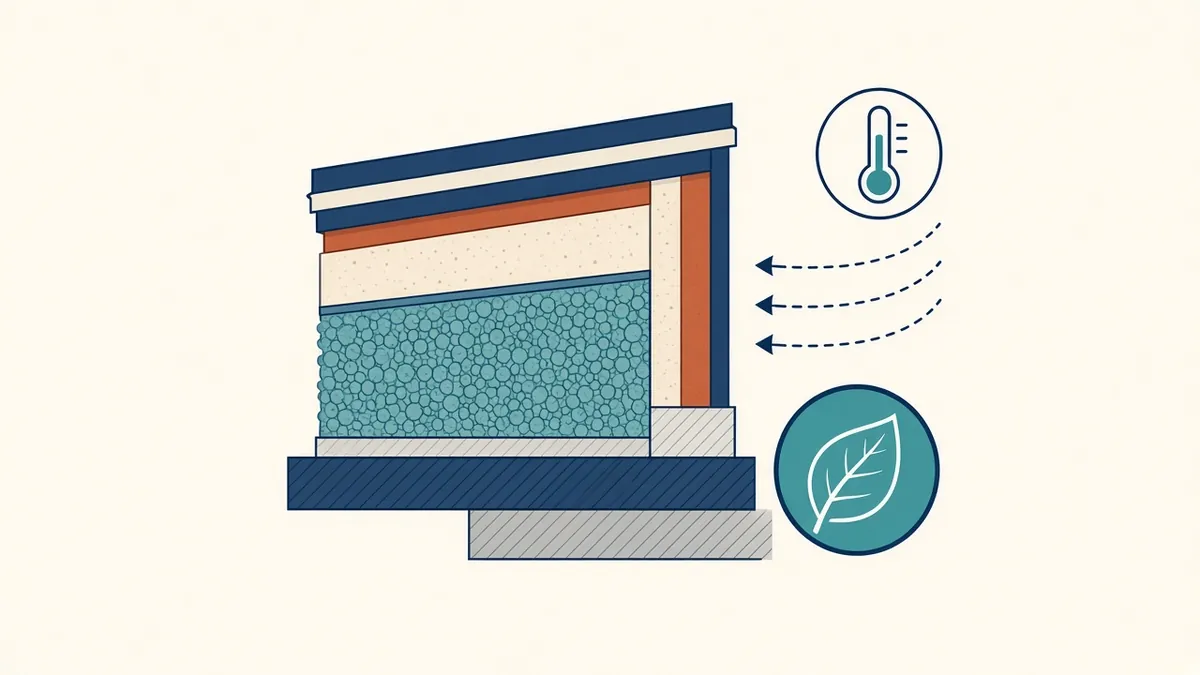
Showing Energy Code Compliance on Drawings
Insulation, glazing and air tightness information reviewers look for.
Read more →
Drawings for UK Building Regulations Approval
What building control needs to see, and how the Approved Documents shape the drawings.
Read more →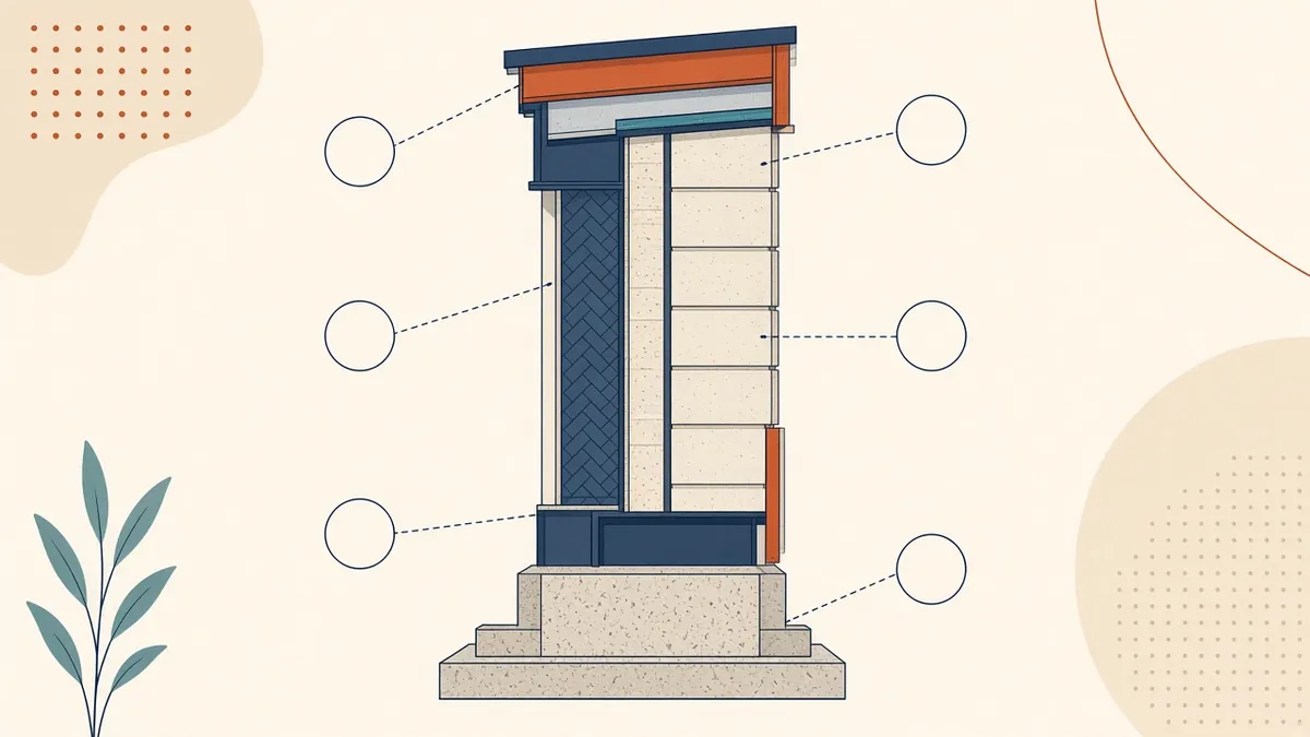
Wall Sections Explained: What to Show and Why
The drawing that ties plans, elevations and details together.
Read more →