
Types of MEP Drawings Explained
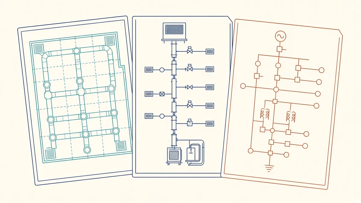
Layouts, schematics, riser diagrams and details all describe the same services in different ways. Each one answers a different question.
MEP engineers and contractors produce many types of drawings. Each serves a different purpose. Understanding them helps Architects read MEP information, coordinate effectively and ask the right questions.
Layout drawings
Layout drawings show services on plan, such as ductwork, pipework, cable containment, lighting and power outlets. They're usually produced for each floor and each system.
Schematics
Schematic drawings show how a system works rather than where it goes. Examples include water system schematics, electrical single-line diagrams and ventilation schematics. They're not to scale and don't show physical routes.
Riser diagrams
Riser diagrams show how services run vertically through a building, often as a schematic of each riser and the floors it serves. They help coordinate shaft sizes and floor penetrations.
Plant room drawings
Plant room layouts show equipment, connections, access and maintenance space. They're often produced at a larger scale.
Sections
Sections through corridors, ceilings and risers show how services fit vertically. They're essential for checking ceiling zones.
Coordinated services drawings
Coordinated or combined services drawings bring several systems together on one drawing, showing how they fit relative to each other and to the structure. They're often produced by contractors during construction coordination.
Builder's work drawings
Builder's work or penetration drawings show openings, sleeves, plinths and supports needed for services. They help the Architectural and structural teams provide for MEP.
Shop drawings
Shop drawings are detailed fabrication and installation drawings produced by subcontractors, showing exact sizes, routes and connections.
Schedules
MEP drawings often include equipment schedules, such as air handling units, fans, light fittings and distribution boards.
Details
Details show specific installations, such as connections, supports or equipment mounting.
Reflected ceiling coordination
Architects' reflected ceiling plans often coordinate MEP elements in ceilings, such as lights, diffusers, sprinklers and access panels.
Reading drawings together
No single drawing tells the whole story. Reading layouts with sections, schematics and Architectural drawings gives a fuller picture.
Check revisions
Ask for what you need
If a congested area isn't clear from the drawings provided, ask the MEP engineer for a section or a coordinated drawing of that area. A targeted request is usually quicker than trying to interpret several separate layouts.
- 01Layout drawings
- 02Schematics
- 03Riser diagrams
- 04Plant room drawings
- 05Sections
- 06Coordinated services drawings
Keep drawing lists current
MEP drawing sets can be large. A current drawing list with revisions helps the whole team find the right sheet quickly and avoid working from superseded information.
Knowing what each MEP drawing shows makes coordination faster and helps Architects spot issues before they reach site.
If your team needs extra production capacity for work like this, take a look at our Architectural production services, or tell us about your project.
Related articles

How Architects Can Read MEP Drawings
What to look for in MEP drawings, from symbols to sizes.
Read more →
MEP Shop Drawings: What Architects Should Check
How shop drawings differ from design drawings, and what to look for in review.
Read more →
Coordinated Services Layouts and Ceiling Coordination
Ceiling zones, routing priorities and coordinated drawings that work on site.
Read more →